Basic usage
This section refers to the example simulations in the simulations/tutorial directory. We create a General configuration in the omnetpp.ini file, which specifies some common parameters of our scenarios. For example, we can specify the number of Resource Blocks to be used in the simulations:
**.deployer.numRbDl = 6
**.deployer.numRbUl = 6
Parameters related to the channel model and feedback computation are located in a separate XML file that needs to be pointed as follows:
**.nic.phy.channelModel = xmldoc("config_channel.xml")
**.feedbackComputation = xmldoc("config_channel.xml")
These files are used to determine physical layer parameters like antenna gain, thermal noise, target BLER etc. and to enable/disable the computation of shadowing, fading, interference from other cells and so on.
A very simple scenario
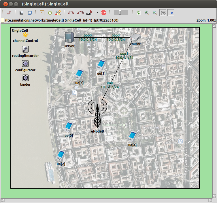
We are ready for setting up our first simulation scenario. In the omnetpp.ini file, we create a new configuration called SingleCell. The network model (defined in the simulations/networks directory) contains one eNodeB serving a variable number of UEs.
[Config SingleCell]
network = lte.simulations.networks.SingleCell
UEs need to communicate with a server located on the internet. Thus, we configure the server so as it runs as many application as the number of UEs. UEs must be associated with the eNodeB, by setting macCellId and masterId parameters (eNodeB IDs are assigned progressively, starting from 1). Mobility parameters (i.e., initial position and mobility type) are also specified both for the eNodeB and the UEs.
*.numUe = ${numUEs=5}

#============= Amount of applications ================
*.ue[*].numUdpApps = 1
*.server.numUdpApps = ${numUEs}

# connect each UE to the eNB
**.ue[*].macCellId = 1
**.ue[*].masterId = 1

#============= Positioning and mobility ============
*.eNodeB.mobility.initFromDisplayString = false
*.eNodeB.mobility.initialX = 300m
*.eNodeB.mobility.initialY = 300m
*.ue[*].mobility.constraintAreaMaxX = 600m
*.ue[*].mobility.constraintAreaMaxY = 600m
*.ue[*].mobility.constraintAreaMinX = 0m
*.ue[*].mobility.constraintAreaMinY = 0m
*.ue[*].mobility.initFromDisplayString = false
*.ue[*].mobility.initialX = uniform(0m,600m)
*.ue[*].mobility.initialY = uniform(0m,600m)
*.ue[*].mobility.speed = 1mps
*.ue[*].mobilityType = "LinearMobility"
#------------------------------------#
We have not yet defined the type of the traffic. We obtain two different configurations by extending the previous one: one for the downlink direction and one for the uplink direction.
[Config SingleCell-DL]
extends=SingleCell

*.ue[*].udpApp[0].typename = "VoIPReceiver"
*.server.udpApp[*].destAddress = "ue["+string(ancestorIndex(0))+"]"
*.server.udpApp[*].localPort = 3088+ancestorIndex(0)
*.server.udpApp[*].typename = "VoIPSender"
*.server.udpApp[*].startTime = uniform(0s,0.02s)
#------------------------------------#

[Config SingleCell-UL]
extends=SingleCell

*.server.udpApp[*].typename = "VoIPReceiver"
*.server.udpApp[*].localPort = 3000+ancestorIndex(0)
*.ue[*].udpApp[*].destAddress = "server"
*.ue[*].udpApp[*].destPort = 3000+ancestorIndex(1)
*.ue[*].udpApp[*].localPort = 3088
*.ue[*].udpApp[*].typename = "VoIPSender"
*.ue[*].udpApp[*].startTime = uniform(0s,0.02s)
#------------------------------------#
In this example, we use VoIP traffic model. The main difference between downlink and uplink is the modules where the VoIPSender and VoIPReceiver applications are located. Destination addresses and port numbers must be set such that one sender application can unequivocally identify the receiver application.
Here's a screenshot of the graphical runtime environment: