Using X2 interface
Once we have built a network composed of a number of eNodeBs, it is likely that we are interested in allowing communication among the latters through the X2 interface. For the sake of clarity, you can find the example described in this section in a new directory, i.e. simulations/x2.
Let us consider a network with three eNodeBs. First of all, the X2Enabled flag must be set. In order to establish an X2 communication with a peer, the eNodeB must have one X2 application for each peer (two, in this case). Remember to assign different port numbers to different X2 applications.
**.x2Enabled = ${x2=true}
*.eNodeB*.numX2Apps = 2
*.eNodeB*.x2App[*].server.localPort = 5000 + ancestorIndex(1)
Note that an X2 application is composed of two independent modules: a server (sending messages) and a client (receiving messages). Thus, modules need to be configured separately (hence the x2App[*].server notation).Since X2 applications run on top of the SCTP transport protocol, we may configure a couple of parameters of the latter. For example, we can disable the Nagle algorithm, which delays the transmissions of small packets (this could be an undesirable behaviour for the X2). In order to speed up the simulation, we could decide to disable the transmission of heartbeats packets (SCTP uses these messages to probe the reachability of an address).
**.sctp.nagleEnabled = false
**.sctp.enableHeartbeats = false
Now, we need to setup the client module of the X2 applications, i.e. destination address of the peering eNodeB. However, this depends on how the eNodeBs are connected to each other (are they connected through point-to-point links or are they connected to a backhaul network?). The current version supports only a X2 backhauling connected as a full-mesh topology.Building a Full-Mesh Topology
We create a configuration called X2-MeshTopology, where each couple of eNodeBs is linked via PPP links. Again, the network definition is in the simulations/networks directory.
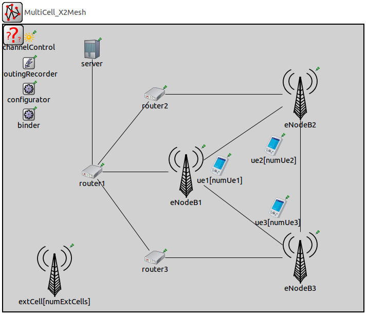
[Config X2-MeshTopology]
network=lte.simulations.networks.MultiCell_X2Mesh

*.eNodeB1.x2App[0].client.connectAddress = "eNodeB2%x2ppp0"
*.eNodeB1.x2App[1].client.connectAddress = "eNodeB3%x2ppp0"
*.eNodeB2.x2App[0].client.connectAddress = "eNodeB1%x2ppp0"
*.eNodeB2.x2App[1].client.connectAddress = "eNodeB3%x2ppp1"
*.eNodeB3.x2App[0].client.connectAddress = "eNodeB1%x2ppp1"
*.eNodeB3.x2App[1].client.connectAddress = "eNodeB2%x2ppp1"
Connecting eNodeBs via a full-mesh topology is just a little more complex. In fact, each eNodeB has one X2 interface per peering eNodeB, thus we need to specify a different gate index for each connection. In this example, eNodeB2 connects to the gate 0 of eNodeB1 and to the gate 1 of eNodeB3.
The X2 is now ready to transport every kind of message. As an example, we implemented a simple CoMP module that exploits X2 functionalities. Please refer to the readme file and to the code for further information.
Prev: Simulating more than one cell Next: Integrating SimuLTE and Veins